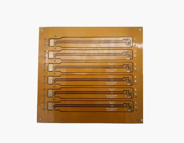
Flexible printed circuit boards have become an important part of modern electronics because they allow engineers to create compact, lightweight, and adaptable circuit designs. From wearable devices and medical equipment to automotive electronics and industrial systems, flexible PCBs help manufacturers develop products that require unique shapes, limited space, and reliable electrical connections. Before moving into mass production, many businesses use a flexible pcb prototype to evaluate their designs, identify potential problems, and confirm that the circuit meets the project’s requirements.
Prototype development allows engineers to test different materials, circuit layouts, component configurations, and mechanical arrangements before committing to larger manufacturing quantities. This process can reduce development risks, improve product reliability, and support more informed engineering decisions.
FastTurn PCBA provides PCB manufacturing and assembly solutions for businesses developing electronic products. Understanding flexible PCB prototypes, their benefits, design considerations, and manufacturing processes can help companies prepare for successful custom circuit development.
What Is a Flexible PCB Prototype?
A flexible PCB prototype is an early version of a flexible printed circuit board created to test and evaluate a circuit design before full-scale production.
Unlike traditional rigid PCBs, which use solid substrates, flexible pcb prototype are manufactured using bendable insulating materials. Polyimide is a common substrate because it offers useful flexibility, thermal stability, and electrical insulation properties.
Flexible circuits can bend, fold, or fit into spaces where conventional circuit boards may be difficult to install. Their construction makes them suitable for electronic products with curved surfaces, moving parts, or strict space limitations.
A prototype helps engineers determine whether a proposed design can meet its electrical, mechanical, and manufacturing requirements.
Common purposes of flexible PCB prototyping include:
- Testing circuit functionality before mass production.
- Evaluating bend radius and mechanical flexibility.
- Checking component placement and connector positions.
- Verifying electrical continuity and signal performance.
- Identifying layout and manufacturing problems.
- Comparing substrate and copper options.
- Confirming the fit of the circuit inside a product enclosure.
- Preparing a validated design for larger production runs.
By testing these factors early, businesses can make necessary adjustments before investing in production tooling, materials, and assembly.
Why Choose FastTurn PCBA for Flexible PCB Prototype Development?
Choosing a suitable manufacturing partner is important when developing custom flexible circuits. Flexible PCB production involves different considerations from rigid PCB fabrication, including substrate handling, copper patterning, coverlay application, and mechanical stress management.
FastTurn PCBA offers PCB manufacturing and assembly solutions for a range of electronic product development requirements. Businesses considering a flexible PCB prototype project should communicate their technical specifications and confirm the manufacturer’s capabilities before production begins.
Support for Custom Circuit Requirements
Every electronic product has different electrical and mechanical requirements. Some designs need a simple single-layer flexible circuit, while others require multilayer construction or specialized component arrangements.
A custom prototype may need to accommodate:
- Unique board outlines.
- Compact circuit dimensions.
- Flexible connector sections.
- Specific bend locations.
- Custom trace widths and spacing.
- Different copper thicknesses.
- Component mounting areas.
- Specialized insulation and protection.
- Application-specific electrical testing.
Clear communication helps the manufacturing team evaluate the design and identify possible production limitations.
Prototype Development for Design Validation
A prototype provides an opportunity to evaluate a circuit before moving forward with a larger manufacturing commitment.
Engineers can test the circuit under expected operating conditions, inspect mechanical fit, and identify areas requiring improvement.
This iterative approach can help reduce the risk of expensive redesigns later in the product development cycle.
Manufacturing and Assembly Considerations
Some flexible PCB designs require components to be mounted directly onto the flexible substrate. Others use rigid sections to support components while flexible sections provide electrical connections between different areas.
For these designs, fabrication and assembly requirements should be considered together.
Customers should confirm whether their selected manufacturing partner supports the required flexible circuit structure, component assembly process, and testing procedures.
Key Benefits of Flexible PCB Prototypes
Flexible PCB prototyping offers several advantages for businesses developing customized electronic products.
Early Design Validation
Testing a physical circuit helps engineers verify whether the design performs as expected.
Simulation and design software can identify many potential problems, but physical prototypes provide additional information about mechanical fit, assembly, connector alignment, and real-world operation.
Early validation helps teams make informed design decisions before committing to larger production quantities.
Reduced Development Risk
Manufacturing a complete product without testing its circuit design can create unnecessary financial and technical risks.
A prototype allows engineers to identify problems with trace routing, component placement, electrical connections, or mechanical flexibility before these issues affect a larger production run.
Although prototyping requires an initial investment, it can help prevent more expensive corrections later.
Improved Product Integration
Flexible circuits can follow curved surfaces and fit into narrow spaces within electronic products.
A prototype allows engineers to confirm that the circuit fits correctly inside the intended enclosure and connects properly with other components.
This is particularly useful for wearable devices, compact sensors, and products with complex internal layouts.
Greater Design Flexibility
Flexible FastTurn PCBA prototypes make it easier to compare alternative circuit arrangements.
Engineers can evaluate different board shapes, connector positions, and folding configurations before selecting a final design.
This flexibility supports product optimization and can help reduce unnecessary design constraints.
Better Preparation for Mass Production
Prototype testing helps establish a clearer understanding of the manufacturing requirements for the final product.
Once the circuit has been validated, the engineering team can refine its design files, material specifications, and inspection requirements.
A well-documented prototype process can make the transition to larger production quantities more predictable.
Types of Flexible PCB Prototypes
The appropriate prototype structure depends on circuit complexity, product dimensions, component requirements, and expected mechanical movement.
Single-Layer Flexible PCB Prototype
A single-layer flexible PCB contains one conductive copper layer supported by a flexible insulating substrate.
This structure is suitable for relatively simple circuits that do not require extensive routing across multiple layers.
Potential applications include basic sensors, simple interconnections, and compact electronic modules.
Single-layer designs can be useful when simplicity, flexibility, and straightforward manufacturing are important priorities.
Double-Layer Flexible PCB Prototype
A double-layer flexible PCB contains conductive copper layers on both sides of the insulating substrate.
The two layers can provide additional routing options and support more complex circuit arrangements.
Electrical connections between layers may be created using plated through-holes or other appropriate interconnection structures.
This configuration can be useful when a single-layer design cannot accommodate the required connections within the available space.
Multilayer Flexible PCB Prototype
Multilayer flexible PCBs contain three or more conductive layers separated by insulating materials.
These designs can support complex routing requirements and more sophisticated electronic functionality.
However, multilayer flexible circuits require careful consideration of thickness, bend locations, material compatibility, and manufacturing complexity.
Engineers should evaluate whether every layer needs to flex and whether the intended bending conditions are compatible with the proposed construction.
Rigid-Flex PCB Prototype
Rigid-flex PCBs combine rigid circuit sections with flexible interconnecting sections.
Rigid areas provide stable mounting surfaces for components, while flexible areas allow the circuit to fold or connect different parts of an assembly.
This structure can reduce the need for separate cables and connectors in some product designs.
Rigid-flex prototypes are particularly useful for compact electronics where space, reliability, and assembly complexity are important considerations.
Flexible PCB Prototype Manufacturing Process
The manufacturing process for a flexible PCB prototype depends on its layer count, substrate material, copper requirements, and design complexity.
Understanding the main production stages helps engineers prepare suitable design files and manufacturing specifications.
1. Design Preparation
The process begins with developing the circuit layout and defining the prototype’s technical requirements.
Designers generally prepare the PCB layout using electronic design automation software.
Important design information includes:
- Board dimensions and outline.
- Copper layer configuration.
- Trace widths and spacing.
- Pad and connector locations.
- Required electrical connections.
- Substrate material.
- Copper thickness.
- Coverlay openings.
- Bend locations and expected movement.
- Component placement, where applicable.
Complete design documentation helps reduce uncertainty during manufacturing.
2. Material Selection
Flexible PCBs commonly use polyimide substrates because of their flexibility and thermal performance.
The selection of substrate, copper type, adhesive system, and protective layers affects the circuit’s mechanical and electrical behavior.
For applications involving repeated bending, engineers should evaluate materials and copper constructions intended for dynamic flexing.
For circuits that bend only during installation, the design requirements may be different.
3. Copper Circuit Formation
The conductive copper layer is patterned to create the required electrical connections.
Manufacturing techniques form the copper traces, pads, and other conductive features according to the approved design.
Trace dimensions and spacing should be appropriate for the electrical requirements and the capabilities of the fabrication process.
4. Coverlay Application
Flexible PCBs often use a coverlay to protect copper traces and provide electrical insulation.
The coverlay contains openings where pads, connectors, or other conductive areas need to remain accessible.
Accurate alignment is important because incorrectly positioned openings can interfere with assembly or electrical connections.
5. Drilling and Interlayer Connections
Double-layer and multilayer flexible circuits may require holes or other structures to connect different conductive layers.
These features must be designed and manufactured according to the selected stack-up and electrical requirements.
Their placement should also account for mechanical stress, especially when the circuit includes areas that will bend during use.
6. Cutting and Finishing
The circuit outline is produced according to the required shape and dimensions.
Additional manufacturing steps may include surface finishing, connector preparation, stiffener attachment, or other operations required by the design.
Stiffeners can provide local support for connectors and components without making the entire flexible circuit rigid.
7. Inspection and Testing
Before a prototype is accepted, it should be checked against the specified requirements.
Inspection and testing may include:
- Visual inspection.
- Dimensional verification.
- Copper trace inspection.
- Electrical continuity testing.
- Insulation resistance testing.
- Connector alignment checks.
- Layer registration verification.
- Functional testing after assembly.
- Mechanical bending evaluation where required.
The appropriate tests depend on the intended application and expected operating conditions.
Important Design Considerations for Flexible PCB Prototypes
A successful flexible PCB prototype requires careful planning because the circuit must satisfy both electrical and mechanical requirements.
Bend Radius
Bend radius is one of the most important factors in flexible circuit design.
A bend that is too tight can damage copper traces, insulation, or other layers.
The acceptable bend radius depends on the circuit’s thickness, copper construction, number of layers, and whether the bend is static or dynamic.
Designers should follow material-specific recommendations and avoid sharp folds unless the construction has been designed and qualified for them.
Copper Thickness
Copper thickness affects electrical resistance, current-carrying capacity, thermal behavior, and mechanical flexibility.
Thicker copper can support certain electrical requirements but may increase the difficulty of bending the circuit.
Engineers should select copper thickness according to current demand, voltage drop, available space, and mechanical requirements.
Trace Routing
Flexible circuits experience mechanical stress when they bend.
Trace routing should account for the intended direction of bending and the location of areas that experience repeated movement.
Rounded corners and suitable routing patterns can help reduce localized stress concentrations.
Where appropriate, designers should avoid placing vulnerable traces directly across highly stressed bend regions.
Substrate Thickness
The total thickness of the flexible circuit influences its flexibility and durability.
A thinner construction may offer greater flexibility, but it must still meet the electrical, thermal, and mechanical requirements of the application.
Engineers should consider the thickness of the substrate, copper layers, coverlay, adhesives, and any stiffeners.
Component Placement
Components are usually less flexible than the substrate itself.
Placing components within regions intended for repeated bending can create reliability problems.
Whenever possible, components should be located in areas designed to remain relatively flat, with flexible sections reserved for interconnection and movement.
Connector and Stiffener Design
Connectors require stable contact areas and sufficient mechanical support.
Flexible circuits may use stiffeners around connector regions to improve handling and help maintain alignment.
The correct stiffener material and thickness depend on the connector, assembly method, and product design.
Applications of Flexible PCB Prototypes
Flexible PCB prototypes are useful across industries that require compact, lightweight, and adaptable electronic circuits.
Consumer Electronics
Smartphones, cameras, tablets, wearable devices, and other consumer products often contain flexible circuits.
These circuits can connect displays, cameras, buttons, sensors, and other components within limited internal spaces.
Prototyping helps manufacturers evaluate fit, connectivity, and assembly requirements before production.
Medical Devices
Medical electronics may use flexible circuits in compact diagnostic equipment, monitoring devices, wearable sensors, and selected medical instruments.
Flexible designs can support ergonomic product shapes and complex component arrangements.
Medical applications require appropriate attention to electrical safety, biocompatibility where relevant, cleaning requirements, and applicable regulatory standards.
Automotive Electronics
Vehicles use electronic circuits in dashboards, lighting systems, sensors, infotainment equipment, and control modules.
Flexible PCB prototypes can help engineers develop circuits that fit curved surfaces or connect components installed in different locations.
Automotive projects may also require environmental testing for temperature changes, vibration, humidity, and long-term operation.
Industrial Equipment
Industrial systems frequently require sensors, compact control units, and specialized electronic modules.
Flexible circuits can simplify connections in assemblies where rigid boards or conventional wiring are difficult to accommodate.
Prototype testing helps confirm that the circuit performs reliably within its intended operating environment.
Aerospace and Defense Electronics
Aerospace equipment often places strict demands on size, weight, electrical reliability, and mechanical durability.
Flexible circuits can help reduce wiring complexity in suitable applications.
These projects may require specialized qualification, detailed material documentation, and application-specific testing.
Internet of Things Devices
Internet of Things products often combine sensors, communication modules, and power management circuits within compact enclosures.
Flexible PCB prototypes allow developers to evaluate circuit placement and integration before manufacturing connected devices at scale.
Common Challenges in Flexible PCB Prototyping
Although flexible circuits offer many advantages, several challenges must be considered during development.
Mechanical Fatigue
Repeated bending can gradually damage copper traces and other circuit layers.
Designers should distinguish between static bending and dynamic flexing, then select an appropriate construction for the expected number of bending cycles.
Limited Space for Routing
Compact flexible circuits may have restricted space for traces and component connections.
Careful layout planning helps engineers balance electrical performance, mechanical flexibility, and board dimensions.
Material Compatibility
Different substrate, adhesive, copper, and coverlay systems may behave differently during fabrication and operation.
Material compatibility should be evaluated for the intended thermal and mechanical conditions.
Assembly Complexity
Flexible substrates can be more difficult to support during component placement and soldering than rigid boards.
Appropriate fixtures, stiffeners, and assembly procedures may be needed.
Prototype-to-Production Differences
A design that works in a small prototype run may require further evaluation before larger production quantities.
Manufacturing consistency, material availability, inspection procedures, and assembly repeatability should be considered before scaling up.
How to Prepare for a Flexible PCB Prototype Order
Preparing accurate technical information can make the prototyping process more efficient.
Before requesting a quotation or beginning production, businesses should organize the following information.
- Finalize the Design Files
Provide the required Gerber files or other accepted fabrication data, along with the drill files and relevant design documentation.
Confirm that the files match the intended board revision.
- Define the Material Requirements
Specify the preferred substrate material, copper thickness, coverlay, and any stiffeners or specialized layers.
If material selection is still open, explain the operating conditions and mechanical requirements so suitable options can be evaluated.
- Identify Bending Conditions
Clarify whether the circuit bends once during installation or experiences repeated movement during normal operation.
Provide the intended bend locations and minimum required bend radius whenever possible.
- Confirm Electrical Requirements
Document trace dimensions, current requirements, voltage limits, impedance requirements where applicable, and any special electrical testing expectations.
- Explain Assembly Needs
If components will be mounted on the flexible circuit, provide the bill of materials, component placement data, and assembly instructions.
Identify any connectors or components that require special mechanical support.
- Discuss Inspection and Testing
Determine which inspections and electrical or functional tests are necessary for the prototype.
Establishing these requirements early helps align manufacturing activities with the project’s goals.
Flexible PCB Prototype vs. Mass Production
Prototyping and mass production serve different purposes within the product development process.
| Feature | Flexible PCB Prototype | Mass Production |
| Primary Goal | Design evaluation and validation | Manufacturing approved products in volume |
| Production Quantity | Usually small | Larger quantities |
| Design Changes | Common during development | Generally controlled through formal revisions |
| Testing Focus | Identifying issues and validating performance | Maintaining repeatability and production quality |
| Cost per Board | Often higher | May decrease with production volume |
| Lead-Time Priorities | Fast evaluation and iteration | Stable scheduling and consistent output |
| Engineering Involvement | Often intensive | Focused on process control and ongoing quality |
A successful prototype provides valuable information for determining whether the design is ready for production.
However, a prototype should not automatically be treated as proof of long-term reliability. Additional qualification may be necessary for products exposed to repeated bending, extreme temperatures, vibration, or other demanding conditions.
How FastTurn PCBA Can Support Custom Circuit Development
FastTurn PCBA offers PCB manufacturing and assembly solutions for businesses working on custom electronic products.
When planning a flexible PCB prototype, customers should communicate their circuit structure, substrate preferences, board dimensions, copper requirements, bending conditions, and testing expectations.
This information helps determine whether the proposed design is suitable for the available manufacturing process.
For more complex projects, customers should confirm the availability of specific flexible PCB materials, multilayer structures, rigid-flex construction, component assembly, and mechanical reliability testing before proceeding.
A well-organized development process can help teams identify potential manufacturing challenges early, refine their circuit designs, and prepare for future production requirements.
Conclusion
Flexible PCB prototypes play an important role in custom circuit development by allowing engineers to evaluate electrical performance, mechanical flexibility, component placement, and product integration before mass production. They can help reduce development risks, improve design decisions, and identify manufacturing challenges at an early stage.
Choosing a suitable flexible pcb prototype solution requires careful attention to substrate materials, copper thickness, bend radius, trace routing, connector design, and testing requirements. These factors influence both the reliability of the prototype and its suitability for the intended application.
FastTurn PCBA provides PCB manufacturing and assembly solutions for businesses developing custom electronic products. By preparing accurate design files and communicating technical requirements clearly, customers can better evaluate suitable prototyping options and plan the next stages of product development.
Whether the project involves consumer electronics, medical devices, automotive systems, industrial equipment, or IoT products, a properly designed and tested flexible PCB prototype can provide a valuable foundation for developing reliable electronic circuits.